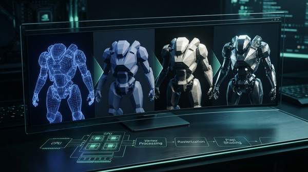
Every frame you see in a game is the end product of a strict, ordered sequence: the graphics rendering pipeline. A render pipeline takes the objects in a scene and displays them on-screen, repeating its steps each time a new frame is generated, as Unity's engine documentation puts it. The process moves data through stages—culling, rendering, and post-processing in Unity's framing, or modeling, illumination, viewing, clipping, projection, scan conversion, and visibility in the classic academic formulation—each stage forwarding its result to the next. Understanding that order, and what each stage does to the data, is the key to diagnosing why a game runs smoothly or stutters.
The Graphics Pipeline: A Step-by-Step Data Flow
Here is the full journey of a single triangle, from raw model data to a shaded pixel on screen. Each stage consumes a specific form of data and hands off a transformed version to the next:
| Stage | Where it runs | Input | What happens to the data | Output |
|---|---|---|---|---|
| Application / Modeling | CPU | Scene objects defined in their own local coordinate systems (object space) | CPU prepares the scene, issues draw calls; modeling transforms orient models within a common world coordinate frame | Scene data in world space, sent to the GPU |
| Vertex processing | GPU | Vertex attributes (position, normal, texture coordinates) pulled from buffer objects | Vertex shader transforms coordinates through model, view, and projection operations; lighting may be computed per vertex | Vertices positioned for projection; per-vertex values such as color ready for interpolation |
| Clipping and culling | GPU | Projected geometry | Objects outside the camera view (frustum culling) or hidden behind others (occlusion culling) are removed; geometry outside the viewable boundary is discarded for efficiency | Only visible, on-screen geometry |
| Rasterization | GPU | Transformed triangles | Continuous primitives are converted into discrete fragments, each corresponding to one pixel of the screen; edge equations interpolate colors and other per-vertex data across the pixels the triangle touches | A grid of fragments with interpolated attribute values |
| Fragment processing | GPU | Interpolated fragment data, textures, lighting parameters | A fragment shader calculates the final RGBA color at each sample position; depth testing and alpha blending resolve overlaps and transparency | Final per-pixel color and transparency values |
| Output merging / post-processing | GPU | Completed pixel buffers | Pipeline modifies the buffers to generate the final frame—color grading, bloom, depth of field | The frame sent to the display |
The crucial insight the table encodes: the pipeline is not a single operation but a relay. Each stage exists to prepare the data for the specific job of the next, and a frame is only as fast as its slowest link.
Application Stage: The CPU's Role
Everything starts off the GPU. The CPU manages the scene's objects, orients models from their private coordinate systems into a shared world space, and issues the draw calls that hand geometry over to the graphics hardware. As Rensselaer's advanced graphics lecture notes describe, models are defined in their own object space, and modeling transforms place them into a common world coordinate frame before any per-pixel work begins. Unity's documentation describes the same starting point from a higher altitude: the pipeline first decides which objects from the scene to display at all. This stage sets up everything the GPU will later chew through, which is why CPU-side scene management shows up so prominently in performance discussions.
Vertex Processing: Shaping the Geometry
Once vertex data reaches the GPU, it arrives as vertex attributes—positions, normals, texture coordinates—read from buffer objects based on setup work the application performed, as the "Following the Data" OpenGL tutorial explains. The vertex shader is best understood as a function called on each of these attribute sets. It applies the modeling, viewing, and projection transformations that position the geometry on screen, and it can assign a color to each vertex, though that color is not applied to any pixels until later. Lighting may be computed here as well: vertices are shaded according to material properties, surface normals, and light sources using local lighting models such as diffuse, ambient, or Phong shading. The output is geometry correctly positioned for the screen, with per-vertex values waiting to be spread across each triangle.
Clipping and Culling: Optimizing Visibility
Before expensive per-pixel work happens, the pipeline throws away everything the viewer cannot see. The lecture notes are blunt about the motivation: clipping avoids degeneracies—don't draw things behind the eye—and improves efficiency by not wasting time on objects outside the image boundary. Unity's documentation gives the modern names for the two main strategies: frustum culling removes objects outside the camera view, and occlusion culling removes objects hidden behind other objects. The RPI notes add a historical wrinkle: older hardware performed full clipping, while modern hardware mostly avoids it, handling only the plane z=0. The practical effect is the same either way—unseen geometry never reaches the rasterizer, so it costs almost nothing.
Rasterization: From Geometry to Fragments
Rasterization is the pivot point of the entire pipeline, the moment continuous vector geometry becomes a discrete pixel grid. As the Wikipedia entry on the graphics pipeline describes, discrete fragments are created from continuous primitives, and each fragment corresponds to one pixel in the frame buffer—hence one pixel on the screen. The hardware determines which pixels are contained in each triangle using edge equations, which also interpolate colors and other per-vertex data across the pixels the triangle touches. Meta's VR developer documentation calls this step converting 3D shapes into a 2D pixel grid for display, and notes that pixel mapping affects image clarity, which is why anti-aliasing exists to smooth the resulting edges. After this stage, there is no more "geometry"—only a grid of candidate pixels, each carrying interpolated values.
Fragment Processing: Coloring the Pixels
Each fragment now gets its final appearance. A fragment shader program computes the floating-point red, green, blue, and alpha contribution to the image at its sample position, using the interpolated attributes, textures, and lighting parameters the earlier stages produced. Shader programs lend themselves to massive parallelism, as the UIC graphics notes observe: each instance works on independent data, produces independent results, and has no side effects, which is exactly why GPUs are built as massively parallel processors. Overlapping geometry also gets resolved here—where polygons overlap, the visible fragment closer to the observer must be determined. Transparency costs extra: as Meta's documentation warns, alpha blending combines fragment colors with underlying pixels, and overlapping transparent objects require more calculations and can impact performance. Finally, the pipeline modifies the pixel buffers through post-processing—color grading, bloom, depth of field—to produce the finished frame.
Performance Bottlenecks: Finding the Slowest Stage
Here is where the mental model pays off for a developer or enthusiast. Because the stages are ordered and each depends on the last, the frame rate is governed by whichever stage is saturated. A scene dense with objects and draw calls stresses the CPU-side application stage, making the game CPU-bound. A scene with enormous geometric detail stresses vertex processing, making it vertex-bound—every one of those vertices must be transformed and lit before anything appears. A scene with high resolution, expensive shading, or many overlapping transparent surfaces stresses fragment processing, making it fragment-bound, and Meta's documentation specifically flags that overlapping transparency is a common fragment-side cost. These are different problems with different fixes: fewer objects and draw calls, simpler geometry, or cheaper shading and lower resolution respectively.
Optimizing for Smooth Performance
Game developers and enthusiasts should identify the primary bottleneck in their graphics pipeline—CPU-bound, vertex-bound, or fragment-bound—to focus optimization efforts effectively. The pipeline's sequential structure makes this diagnosis straightforward in principle: the slowest stage sets the pace for the whole frame, so effort spent accelerating a stage that already has headroom buys nothing. The measurable indicator to watch is frame rates alongside GPU and CPU utilization metrics, which pinpoint the slowest stage and guide targeted adjustments to scene complexity, shader complexity, or resolution. A game running at a low frame rate while the CPU sits at full load and the GPU idles has an application-stage problem; a GPU pegged at 100 percent with a modest frame rate points at vertex or fragment work. Read the pipeline in that order—setup, geometry, then pixels—and the stutter stops being a mystery.